You can play with pentominoes on surfaces at https://pentominoes.river.me!
On a rectangle, a set of 5 adjacent squares uniquely defines a pentomino. This may seem obvious; after all, by definition a pentomino tile is a collection of 5 adjacent squares that’s unique up to rotation or reflection.
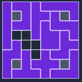
For example, here’s a board with one empty tile; clearly, only the W tile can fit here:
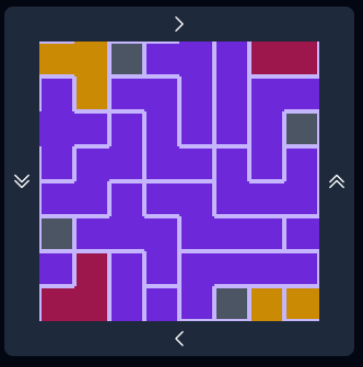
But if we embed the board on a nonorientable surface, this is no longer true. Here’s an example on a projective plane that demonstrates this:
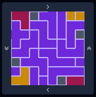
And here’s that solve, but with the P and T tiles swapped:
Finally, let’s take a look at the board with both P & T removed, so we can see what the empty spaces look like:
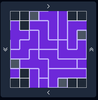
(Exercise to the reader: which other pentominoes, if any, can fit in this same empty space?)
Orientable vs nonorientable surfaces
Feel free to skip this section if you’re already familiar with orientability.
Take a strip of paper and glue the edges together so that it makes a ring. Then take a pen and place it on the paper somewhere. Start turning the paper below the pen until you get back to the starting point and then look at what you’ve drawn. Unless something went horribly wrong, you’ll end up with one side with pen mark and one side that’s blank. That’s because a piece of paper has two sides, and we glued the strip together in an orientable manner.
Let’s now repeat this (thought) experiment, but this time there’s a twist - literally. This time, before gluing the paper together at its edges, give the entire band one (1) twist. You should have the top of the paper on one side glued to the bottom on the other side, and vice versa.
Once again, hold up a pen to it and draw. This time, you’ll end up with a pen mark everywhere!
In our 2nd example, what we’ve created is known as a Möbius Band or Möbius Strip (I’m not gonna keep typing the umlaut after this). The Mobius band is nonorientable, that is, it doesn’t have distinct sides. In topology, nonorientable surfaces are, roughly speaking, surfaces that contain Mobius bands.
In Pentominoes on Surfaces, you can play on any surface that has a fundamental polygon with 4 sides (i.e. has genus of 1 or 0). The available surfaces can be divided into two types, “orientable” and “nonorientable.”
(Note that the rectangle, cylinder, and Mobius band are not technically surfaces, but that doesn’t stop them from being fun to solve on.)
Orientable surfaces include:
- Rectangle
- Cylinder
- Sphere
- Torus
Nonorientable surfaces include:
- Mobius band
- Projective Plane
- Klein Bottle
Graphs on surfaces
In this section, we’re talking about graph theoretical graphs, or collections of vertices connected by edges.
If you know the term “four-color theorem,” then you know a bit about embedding graphs already. The four-color theorem states that every planar graph can be properly colored with at most 4 colors. The “planar” in “planar graph” means “embeddable on the plane (or sphere) so that no two edges intersect.” (Embedding a graph on a plane is topologically equivalent to embedding it on the sphere.)
But not all graphs can be embedded on the plane without having edges intersect. For example, try to draw this graph so that all vertices & edges are still there, but no two edges intersect each other:
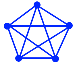
Spoiler: You can’t. (That graph is called K_5, the complete graph on 5 vertices.1)
But what if we tried to draw it on a Mobius band? Here’s a representation2 of a Mobius band:
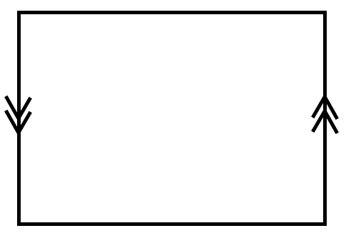
Imagine taking the left & right sides of this diagram, applying a twist, and then gluing them together. So if you start drawing a line towards the bottom of the left side, it emerges at the top of the right side; and a line towards the top of the left side emerges at the bottom of the right side. For example, here’s a straight, unbroken line:
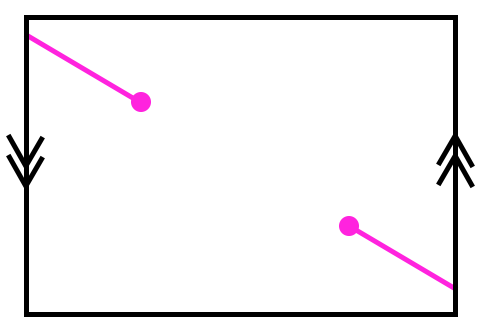
Because it’s pretty hard to physically draw on a Mobius band, we use a diagram that represents it, and then draw on that instead.
Copy that image into your favorite image editor and see if you can embed K_5 now. You should be able to.
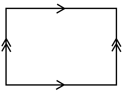
You can also embed K_5 on the torus. Here’s a representation of a torus:
Here are possible answers. On the left side is a Mobius band, and on the right side is a torus.
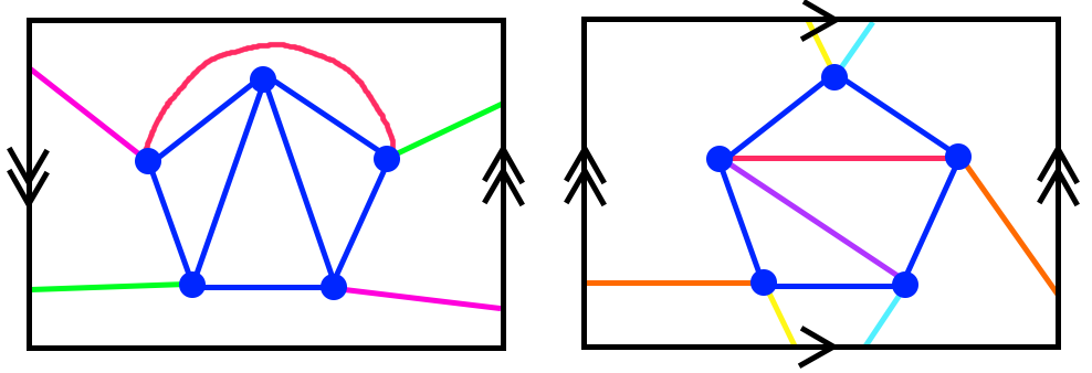
The edges are colored to make them easy to follow across the boundaries of the polygon, and not with any intention of “properly” coloring. In both cases each vertex is connected to the other 4, and no edges cross each other.
A pentominoes board as a graph
When a graph is embedded in a surface, we can talk not only about vertices and edges, but also its faces. Informally, a face is a portion of the surface outlined by a series of consecutive edges & vertices.3
That makes our pentomino board a graph. But it might not be the one you think it is.
This is a hypothetical graph representation of a 2x2 Pentominoes board. Indeed, we could give some formal definition that maps this graph to that of a rectangle grid, saying something about how each face (other than the de facto face created by the rest of the plane except for the area inside of the grid) represents a tile; edges represent the border between 2 faces (again, except for the edges incident to the “outside” face); and what a vertex represents depends on its degree (number of incident edges).
That was a lot of text and I didn’t even give a full definition, I just outlined one. There must be a better way to do this!
In this version, instead of trying to use faces to represent the places a Pentomino can go, we’re using vertices for the same purpose. Two vertices are adjacent to each other if there’s an edge connecting each other.
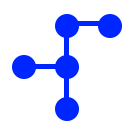
To further demonstrate this arrangement, here’s a depiction of the F tile using this notation:4
This idea of interchanging faces and vertices is formalized in graph theory with the idea of dual graphs.
Pentominoes on surfaces
Now let’s look at a couple surfaces. We’re going to use a 4x4 grid in this section, because a lot of symmetries are hard to see in a 2x2 grid.
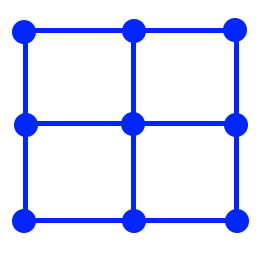
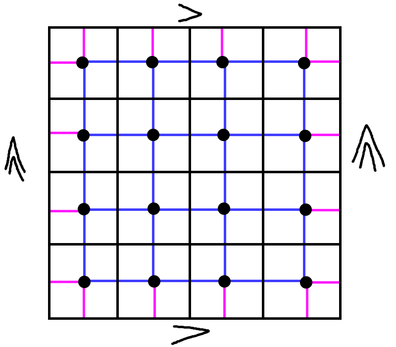
First, here’s the grid as a rectangle, no surface:

Each vertex, in black, is situated in the middle of a grid square, and then we draw blue lines connecting all adjacencies.
What if we’re on a torus, though? Suddenly a lot more vertices are adjacent to each other than there were before:
So the graph we’re embedding on a torus is not the same as the graph we’re embedding on a rectangle.
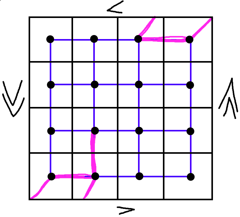
Here’s the projective plane:
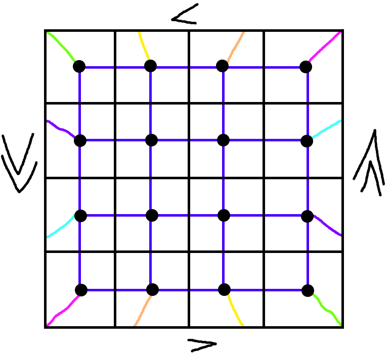
In particular, notice that the corners are distinguishable from all other nodes because they have degree 3 (there are 3 edges incident to them, 3 other vertices adjacent).
But wait! There are two different ways that a line can be drawn, right?
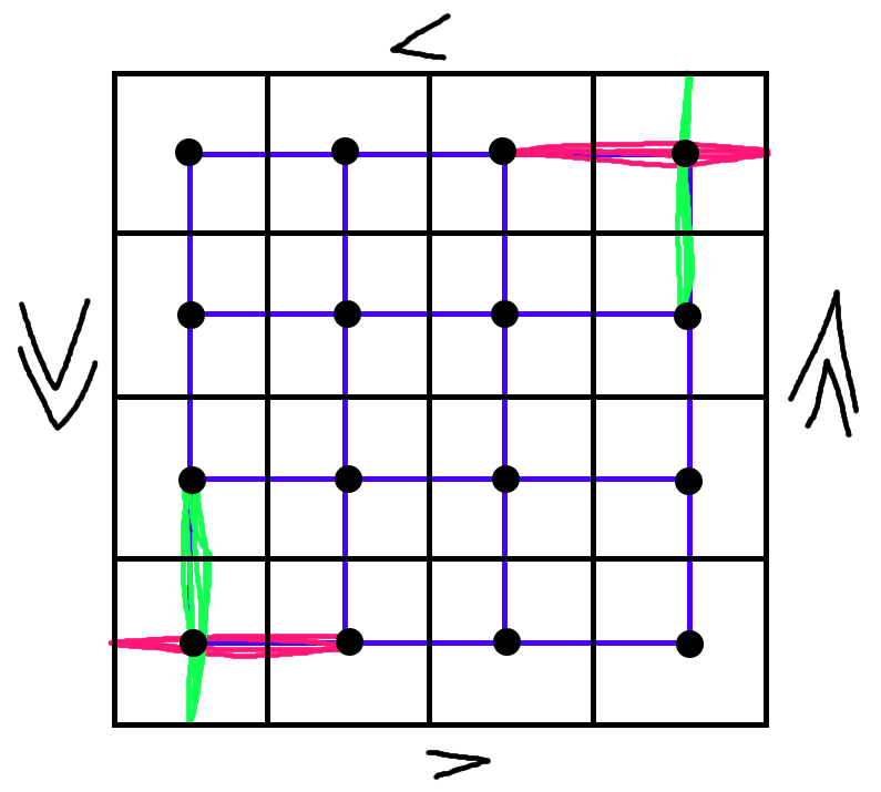
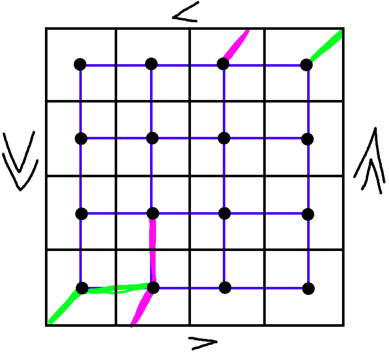
Ah, no. Graphs don’t care about geometry. Here’s how this actually looks:
There are 5 edges colored in here - two in green, two in pink, and one in both pink and green.
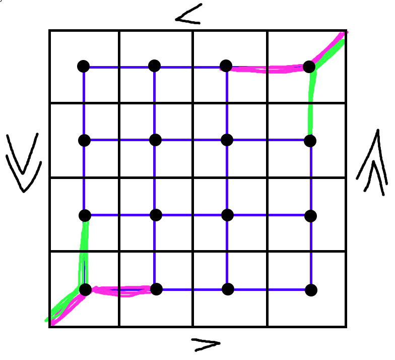
As a consequence of this unique geometry at the corners, there are some tiles that cannot be placed in the corner of a grid on a nonorientable surface, period. For example, let’s look at what happens when we place an X in the corner of a projective plane:
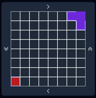
Here, the top and right squares of the X are both wrapping around the edge of the grid to the same square, and the tile is conflicting with itself! (Conflict shown in red in the bottom-left corner.)
We’re cheating a bit
Geometry DOES exist in the original pentomino grid. If it didn’t, then I, L, N, U, V, W, and Z would all be identical. Indeed, the only distinct tiles would be F, I, P, T, and X. So our tile-to-graph conversion is a bit illegal.
We’re allowed to ignore geometry a bit, though. Specifically, we can cheat geometry at the two vertex tiles, but nowhere else.
If we wanted to be more precise with our conversion of grid to graph, we’d have to do something like take the “convex hull” of a tile in the original grid, and attach an edge-coloring as follows:
- If both vertices the edge is incident to are part of the tile, it gets color 1
- Otherwise it gets color 2
Two tiles can go next to each other if they don’t share edges colored 1, but edges of color 2 are ignored.
In my Pentominoes code, this is more or less what I do - although I stick with coloring faces as the model, each pentomino is defined by its convex hull. For example, here’ the F tile (note, 2 represents the center of the tile, where it will be placed when you click on the grid):
|
|
The P & T tiles
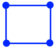
Here is the P tile (a 4-cycle + 1 extra vertex):
And here is the T tile (two paths of length 3 that meet in the center of one (pink), and farthest corner of the other (green)):
And so we have 2 different tiles fitting into the same vertices - because we’re able to “bend” one of them at the corner that only has degree 3.
Conclusion
Combining a rigid space with a surface leads to very weird behavior, but we can still somewhat model using graphs. Of course, the analogy of pentominoes to graphs doesn’t work completely, but it does help to illuminate what is going on at these truly bizarre corners.
One last thing to notice - if you do a solve on a torus, you can always translate it a couple squares up or down on its fundamental polygon. But this does not work when you’re solving on a nonorientable surface.
-
Specifically, this representation is a fundamental polygon. ↩︎
-
If you get into a Wikipedia rabbit hole here, please don’t confuse Orientation (graph theory) with Orientability, a property of topological surfaces. They are completely unrelated. ↩︎
-
This representation is slightly incorrect, because geometry exists, but we’ll get to that later. ↩︎